Corrosion Inhibitors in Gas Production Systems: CO₂, H₂S, Wet Gas, MEG and Dosage Calculations
Corrosion Control · Technical Guide
Corrosion-inhibitor treatment in gas production must be defined against the phase that actually wets the steel. Gas rate may be reported in SCFD or MMSCFD, while inhibitor may be injected in L/day or US gal/day and the treatment specification may be expressed per gas volume, per produced-water volume or per total liquid. These bases are not interchangeable.
1. Why wet gas corrodes
Dry hydrocarbon gas is not equivalent to a corrosive aqueous electrolyte. Internal corrosion becomes important when free or condensed water contacts carbon steel and dissolves corrosive species such as CO₂, H₂S, organic acids or oxygen contamination. Corrosion severity depends on acid-gas partial pressure, temperature, water chemistry, pH, flow regime, velocity/shear and corrosion-product films.
2. Sweet CO₂ corrosion
CO₂ dissolves into the aqueous phase and participates in carbonate chemistry that supports electrochemical corrosion. Under favorable conditions FeCO₃ can precipitate and become partly protective, but film protectiveness depends on temperature, pH, supersaturation, flow and surface conditions. CO₂ partial pressure alone is therefore not a complete corrosion-rate predictor.
3. Sour and mixed CO₂/H₂S systems
H₂S changes both aqueous electrochemistry and corrosion-product chemistry. Iron-sulfide phases may form and can alter corrosion rate and morphology. Mixed CO₂/H₂S behavior is condition-dependent; it is not scientifically safe to state that H₂S always increases or always decreases general corrosion. Sour service also introduces cracking/material-selection issues that are distinct from simple mass-loss corrosion.
4. Bottom-of-line versus top-of-line corrosion
Bottom-of-line corrosion occurs where liquid water accumulates and wets the lower pipe wall. Top-of-line corrosion (TLC) can occur when water condenses on the cooler upper wall of wet-gas pipelines, particularly under stratified or wavy-stratified flow. Conventional non-volatile liquid-phase film-forming inhibitors can remain predominantly in the bottom liquid and may reach the upper condensate film poorly. Condensation rate, volatile acids, gas temperature, flow regime and inhibitor transport therefore matter in TLC.
5. Film-forming corrosion inhibitors
Common oil-and-gas film-forming inhibitor families include imidazoline/amidoamine derivatives, fatty amines and salts, quaternary ammonium compounds and related nitrogen-containing formulations. Hydrophobic tails and polar/charged head groups can promote adsorption and formation of a barrier at the steel/water interface. Formulation, protonation, partitioning and surface condition affect performance.
6. Partitioning is critical
The injected concentration is not necessarily the concentration available at the corrosive steel surface. An inhibitor can partition among gas, condensate/hydrocarbon and water phases. A product with excellent laboratory adsorption can underperform if it remains in the wrong phase or does not reach intermittently wetted surfaces.
7. MEG-containing gas systems
Monoethylene glycol (MEG) is widely used for hydrate management in gas systems. Changing MEG concentration changes the aqueous solvent environment, water activity and physical properties and can alter corrosion behavior and inhibitor availability/partitioning. Corrosion-inhibitor qualification should therefore use representative MEG/water ratio, salts, temperature, acid-gas loading and contaminants rather than assuming performance in simple brine transfers directly to a MEG loop.
8. Flow, shear and slugging
Higher velocity and wall shear can alter mass transfer and inhibitor-film persistence. Slug flow produces changing liquid holdup and intermittent wetting. These hydrodynamic effects help explain why a static test alone cannot represent every wet-gas pipeline.
9. Continuous versus batch treatment
Continuous injection aims to maintain protection during operation. Batch treatment can establish or replenish a persistent film in suitable systems. The choice depends on flow regime, water availability, inhibitor persistence, pigging capability, injection hardware and corrosion threat. Neither strategy is universally superior.
10. Define the dosage basis before calculating anything
For gas service, write the treatment basis explicitly. Examples include US gal/MMSCF, L/MMSm³, ppm v/v on produced water, ppm v/v on total liquid, or ppmw. Calling all of these “ppm” is incorrect.
11. Gas-basis calculation: US gal/MMSCF
If treatment is specified as US gallons of inhibitor per million standard cubic feet of gas:
Chemical (US gal/day) = Gas rate (MMSCFD) × Treatment rate (US gal/MMSCF)
Chemical (L/day) = US gal/day × 3.785411784
Example: 35 MMSCFD at 0.20 US gal/MMSCF requires 7.00 US gal/day = 26.50 L/day.
12. Reverse gas-basis calculation
When gas rate and actual pump rate are known:
Treatment rate (US gal/MMSCF) = Chemical (US gal/day) / Gas rate (MMSCFD)
For 35 MMSCFD and 20 L/day, 20 L/day = 5.283 US gal/day, so treatment rate ≈ 0.151 US gal/MMSCF.
13. Water-basis ppm
If the programme defines inhibitor dosage on produced water:
ppm v/v = Chemical (L/day) / Water (L/day) × 10⁶
Required chemical (L/day) = Water (L/day) × target ppm / 10⁶
Example: 500 bbl/day water = 79,493.65 L/day. At 25 ppm v/v, required inhibitor = 1.99 L/day. This calculation is valid only when the treatment basis is explicitly the water phase.
14. Total-liquid or condensate basis
The same volumetric-ppm equation can be used when the contractual basis is total liquid or condensate, but the denominator must be the defined phase flow. Water-basis ppm and total-liquid-basis ppm can differ greatly in a gas field with low water cut.
15. Mass-basis ppmw
ppmw = Chemical mass flow / treated-stream mass flow × 10⁶
If field rates are volumetric, density is required to convert each relevant stream to mass flow. Do not convert v/v ppm to ppmw without density information.
16. SCF, Sm³ and Nm³ require a reference condition
A standard cubic foot or standard/normal cubic metre is a gas volume referenced to specified temperature and pressure. The exact reference conditions must be known before high-accuracy conversion between SCF, Sm³ and Nm³. A calculator should therefore avoid silently treating all “standard” and “normal” volumes as identical.
17. Gas Corrosion Inhibitor Dosage Calculator
Use this calculator when the treatment specification is explicitly stated on a gas-throughput basis such as US gal/MMSCF. It also provides the reverse calculation from actual pump rate to treatment rate.
Gas basis: required inhibitor rate
Reverse: actual treatment rate
Water basis: ppm v/v
Important: these calculations convert a treatment rate that has already been technically selected. They do not prescribe the correct inhibitor dose. Published field practice uses different bases and rates depending on wetness, water rate, velocity, inhibitor chemistry and monitoring response.
18. Quick gas-rate table
| Gas rate (MMSCFD) | 0.10 gal/MMSCF | 0.20 gal/MMSCF | 0.50 gal/MMSCF |
|---|---|---|---|
| 5 | 0.5 gal/d | 1.0 gal/d | 2.5 gal/d |
| 10 | 1.0 | 2.0 | 5.0 |
| 25 | 2.5 | 5.0 | 12.5 |
| 50 | 5.0 | 10.0 | 25.0 |
| 100 | 10.0 | 20.0 | 50.0 |
18. Laboratory evaluation
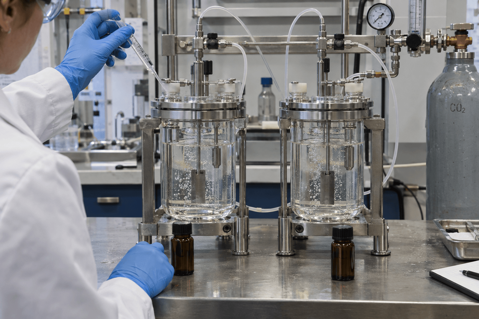
Screening should represent the relevant aqueous chemistry, CO₂/H₂S condition, temperature, pressure and hydrodynamics. Depending on the question, methods can include weight-loss/wheel testing, LPR, rotating-cylinder/cage methods, HPHT autoclaves and flow loops. Static ranking should not be assumed to predict film persistence under high shear.
19. Field monitoring
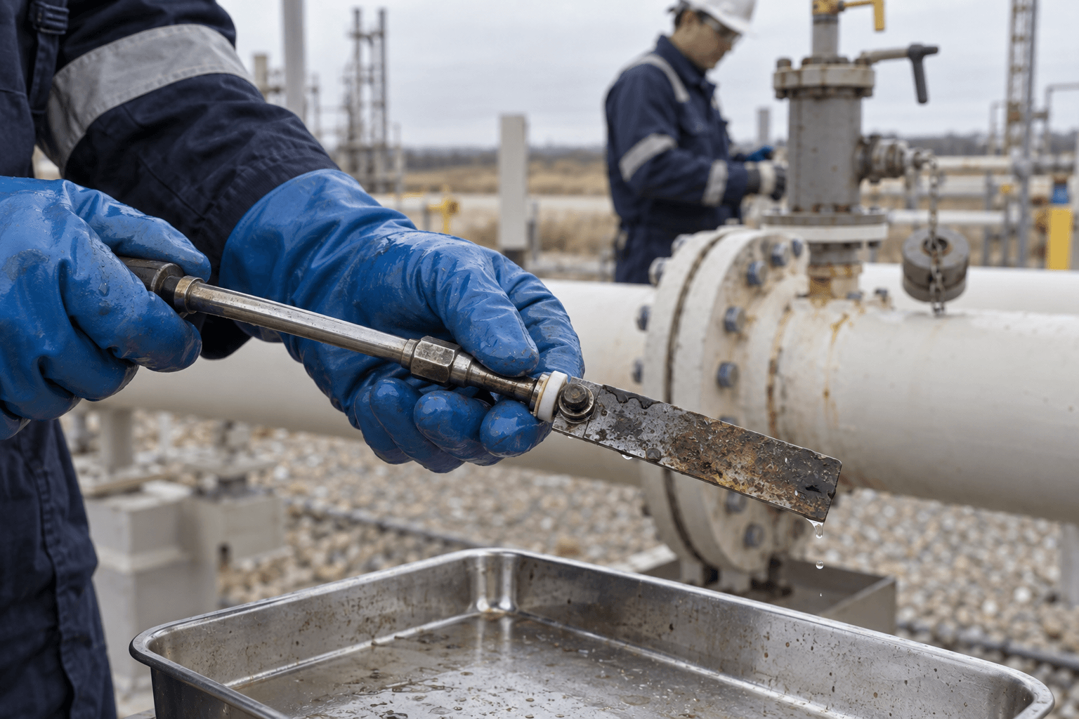
Useful evidence can include corrosion coupons, LPR or ER probes, inspection data, iron trends where interpretable, water chemistry, inhibitor residual/availability where a validated method exists, injection-system verification and operating data. No single measurement proves treatment success in every system.
20. Why a good gas inhibitor can fail in the field
- Wrong dosage basis or unit conversion
- Inadequate chemical delivery or pump calibration
- Poor partitioning into the corrosive aqueous phase
- Insufficient coverage of top-of-line condensate
- Film removal or poor persistence under shear/slugging
- MEG or brine compatibility differences
- Changed CO₂/H₂S partial pressure, temperature or water rate
- Laboratory test conditions that did not reproduce the field
21. Practical selection workflow
- Define dry/wet gas condition and corrosion location.
- Characterize water/condensate/MEG and acid gases.
- State the treatment basis and units explicitly.
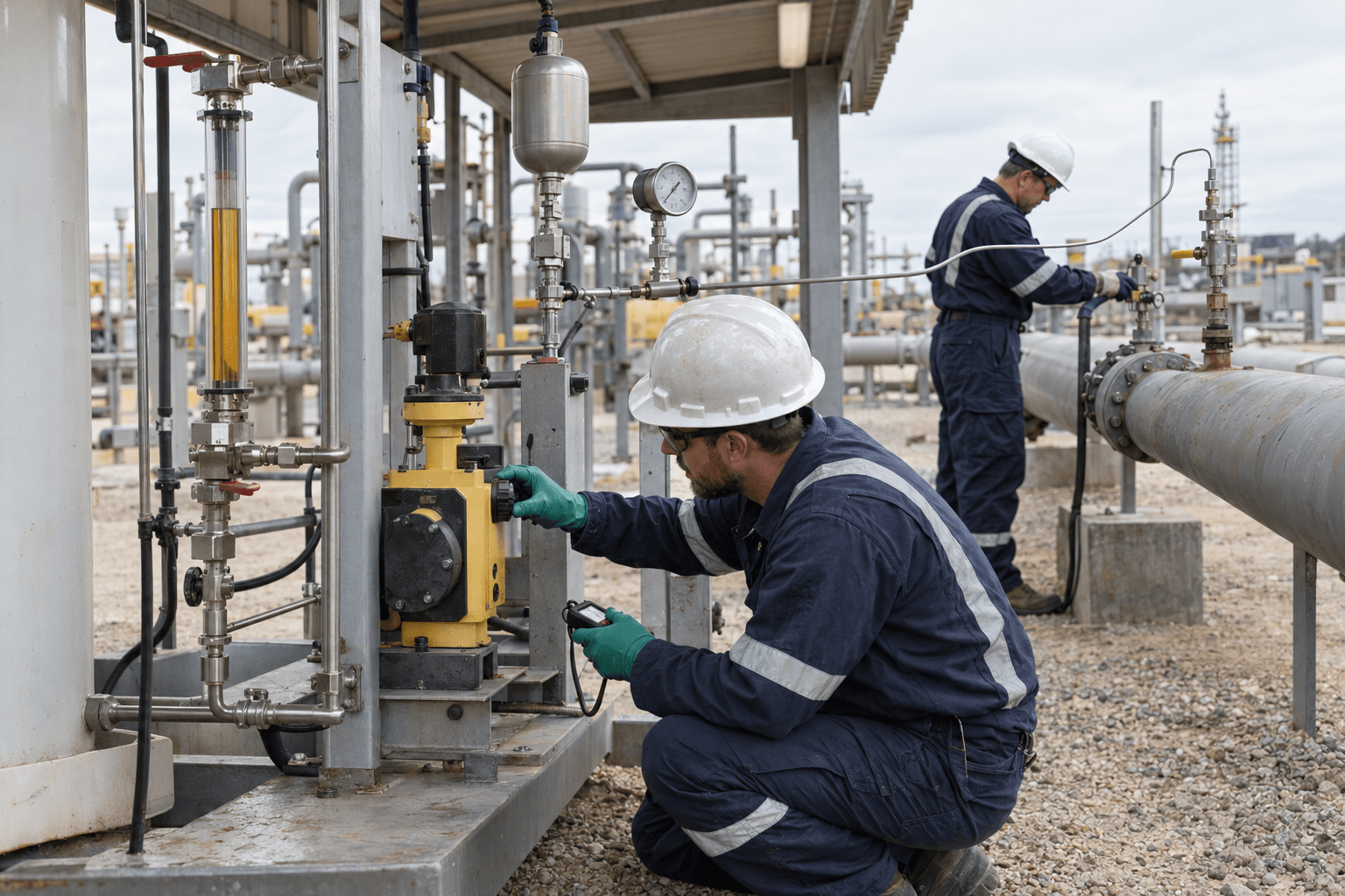
- Verify injection hardware and actual chemical consumption.
- Screen candidate chemistry under representative conditions.
- Challenge film persistence under relevant hydrodynamics.
- Conduct a controlled field trial with corrosion and process KPIs.
- Optimize dose only after technical performance is demonstrated.
Frequently asked questions
Can I convert MMSCFD directly to ppm?
No. MMSCFD is a gas volumetric flow rate. A dosage such as gal/MMSCF can be calculated directly, but “ppm” requires a clearly defined phase and basis.
Should corrosion inhibitor be dosed on gas or water?
There is no universal basis. The treatment programme must define whether dosage is related to gas throughput, produced water, total liquid or another stream.
Does dry gas need film-forming inhibitor?
The internal-corrosion threat depends strongly on whether a corrosive aqueous phase can form or contact the steel. Water dew point, condensation and process upsets must be considered rather than assuming all gas service is either safe or corrosive.
Conclusion
Gas corrosion-inhibitor programmes require two disciplines at the same time: correct corrosion chemistry and correct treatment arithmetic. CO₂/H₂S, condensed water, MEG, hydrodynamics and inhibitor partitioning determine whether the steel surface is protected, while the dosage basis determines whether the intended chemical amount is actually being injected.
Always state the denominator. “0.2 gal/MMSCF,” “25 ppm on water” and “25 ppm on total liquid” describe different treatment programmes.
Technical references
- Askari, M.; Aliofkhazraei, M.; Ghaffari, S.; Hajizadeh, A. Film former corrosion inhibitors for oil and gas pipelines – A technical review. Journal of Natural Gas Science and Engineering 2018, 58, 92–114. DOI: 10.1016/j.jngse.2018.07.025.
- Obot, I. B. et al. A review study on the challenges and progress of corrosion inhibitor testing under extreme conditions in the oil and gas industries. Geoenergy Science and Engineering 2023, 211762.
- Al-Moubaraki, A. H.; Obot, I. B. Top of the line corrosion: causes, mechanisms, and mitigation using corrosion inhibitors. Arabian Journal of Chemistry 2021, 14, 103116. DOI: 10.1016/j.arabjc.2021.103116.
Related Horizons Apex resources: Imidazoline vs. Quaternary Ammonium Corrosion Inhibitors, Oilfield Corrosion Inhibitor Testing, and Why Corrosion Inhibitors Fail in the Field.